Ingressus Metal Casing Setup
Introduction
Ingressus controllers are designed to control access for a one-door (Ingressus I), two-door (Ingressus II) and four-door environment (Ingressus IV). With Ingressus, a user needs to verify his identity at a Wiegand terminal or an RS485 reader with fingerprint, card, password or any combination of credentials during entry and exit. The Ingressus has to finalize the user’s identity before granting him access to a particular area. The transaction records will be saved into the Ingressus’s inbuilt memory and sent to the software for further processing. Multiple Ingressus installations can be centralized via IP or RS485 connection in a computer installed with the bundled Ingress software. Each Ingressus I works independently at its access point; however, the data is centralized from all Ingressus controllers to give a better and complete picture of the entire security level.
Ingressus controllers are designed to control access for a one-door (Ingressus I), two-door (Ingressus II) and four-door environment (Ingressus IV). With Ingressus, a user needs to verify his identity at a Wiegand terminal or an RS485 reader with fingerprint, card, password or any combination of credentials during entry and exit. The Ingressus has to finalize the user’s identity before granting him access to a particular area. The transaction records will be saved into the Ingressus’s inbuilt memory and sent to the software for further processing. Multiple Ingressus installations can be centralized via IP or RS485 connection in a computer installed with the bundled Ingress software. Each Ingressus I works independently at its access point; however, the data is centralized from all Ingressus controllers to give a better and complete picture of the entire security level.
To set up the Ingressus controller, a 12VDC power supply and backup battery are needed to operate and function well as access control. As these components are needed, the Metal casing is essential to place these components for better maintenance and safety. Therefore, FingerTec provides a specific metal casing accessory for the Ingressus Controller to ease installation. Here are steps for Ingressus metal casing setup:
 Ingressus Metal Casing Set
Step 1 : Join the back and the front metal casing

Step 2: Join the right side of the metal casing


Step 3 : Join the top metal casing


Step 4 : Join the bottom metal casing


Step 5 : Prepare the 8 casing Screws
Step 6 : Screw every corner of the metal casing

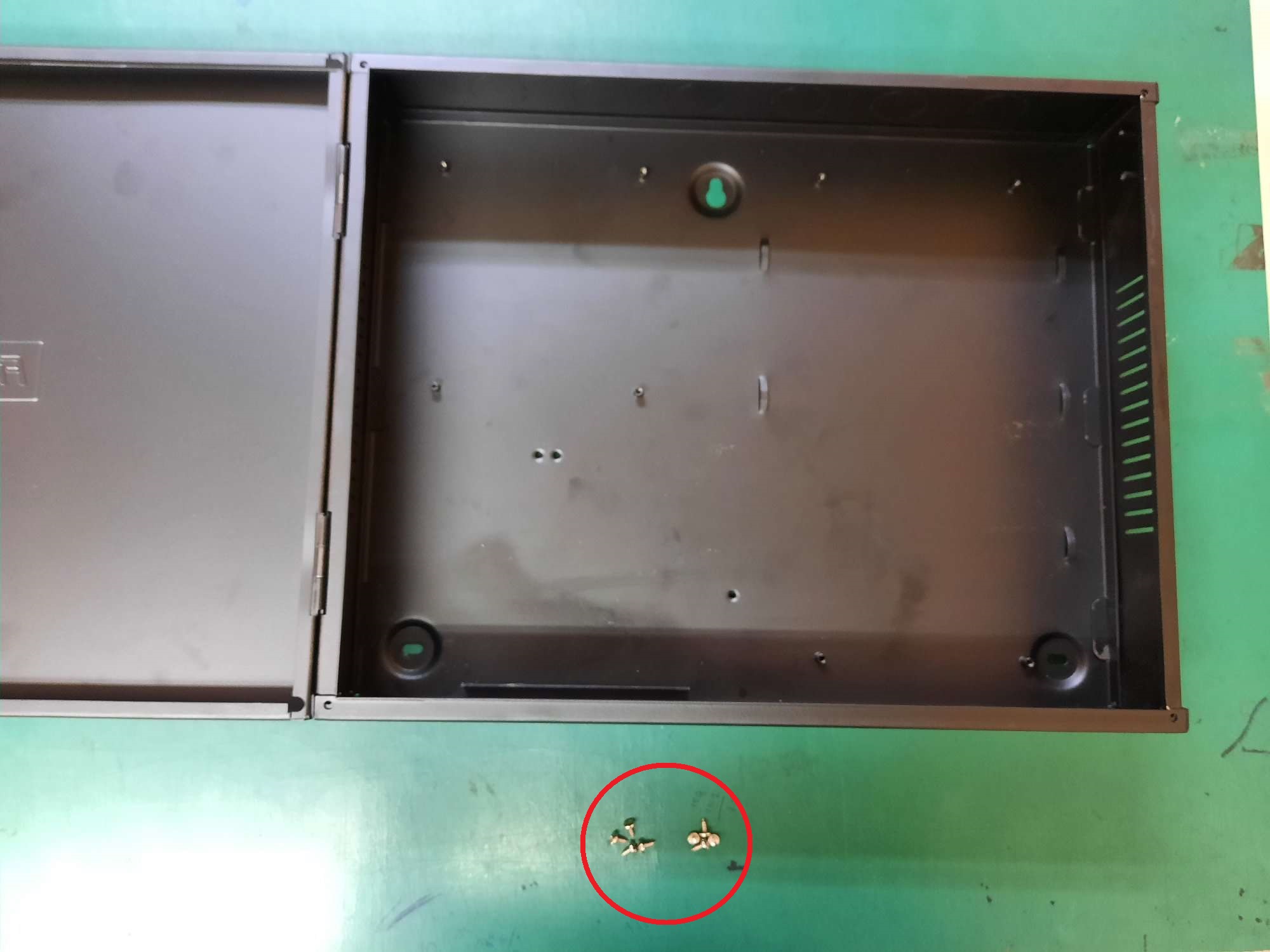
Step 7 : Prepare 4 holder screws

Step 8 : Flip the power supply

Step 9 : Align the bracket with the power supply, screw hole and screw it with 2 Holder screws
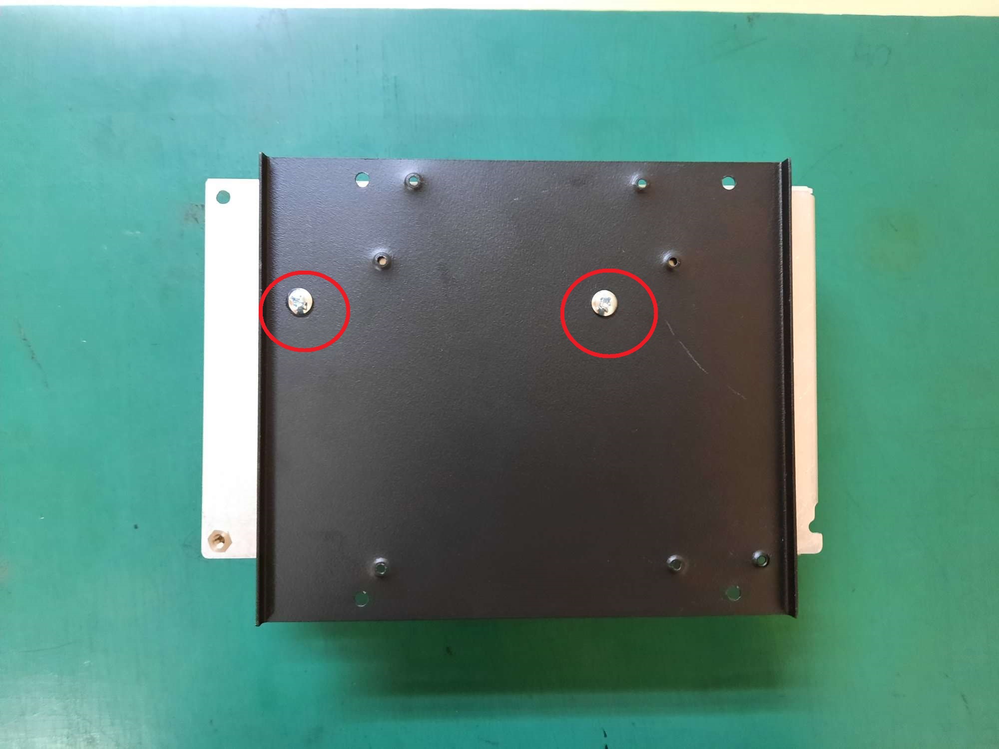
Step 10 : Screw the bracket to metal casing with 2 holder screws

Step 11 : Prepare 2 Holder screws

Step 12 : Screw Bracket at the metal casing with 2 Holder screws

Step 13 : Slot in the ingressus at the bracket where Ingressus have DIN Rail slot at the back

Step 14 : Prepare 2 Casing screws

Step 15 : Mount battery with Z bracket by screwing it with the Casing screw

Note: If some of the screenshots or steps viewed here are different from the ones in the current system, this is due to our continuous effort to improve our system from time to time. Please notify us at info@timeteccloud.com, we will update it as soon as possible.
Related Articles
How to Setup Interlocking in Ingressus
Introduction For higher-level security, interlocking is the fundamental parts of door access security where two doors are interconnecting, where each of the doors must entirely close before one could access another door. This feature is to prevent ...How To Setup Ingressus 2 Control Double Leaf Door
Introduction Some companies use double-leaf doors in their premises or offices as the main entrance. Most of them require a simple system that allows both doors to open simultaneously, making it easier for people to enter and exit the office. In this ...Activating the Door Closure Delay Siren in Ingressus
Introduction Security is an important aspect in every organization nowadays. Improper security measures may cause bigger problems such as robbery, data theft or even endanger the safety of a person. Even with the proper access control products ...Timeline 100 External Bell Connection and Setup
External bell is used to alert or remind user of break time, shift change or for safety purposes. It is generally installed in schools, factories, warehouses and other organizations. A schedule bell specifies the start time and duration of one or ...Ingressus 4 In/Out Device : K-Kadex / I-kadex pair with R2c / R3c
Introduction Ingressus IV is a controller that supports access control for 4 doors. By default, the Ingressus IV only supports 1 Wiegand device for each door as In-device. However, by using RS485 slave, we can make the setup to have an Out-device. ...